Posted by SainSmart on


Need an excuse in a hurry?
Look no further than the Excuse Generator.
Look no further than the Excuse Generator.
Step 1: What You Need / Wire it Up
We are using:
Arduino Uno
LCD Module (HD44780 compatible)
Potentiometer
Tilt Switch
220 Ohm Resistor (Red-Red-Black-Black) / (Red-Red-Brown) or 470 Ohm or 560 Ohm is fine too
Wire up the LCD module to the Arduino as listed below and illustrated in the Diagrams.
Don't forget to wire in the Pot and the Tilt Switch too as shown.
Wire up the LCD Module as follows:
LCD pin (1) / Vss -> Gnd
LCD pin (2) / Vdd -> 5V
LCD pin (4) / RS -> 12
LCD pin (5) / R/W -> Gnd
LCD pin (6) / E -> 11
LCD pin (11) / D4 -> 5
LCD pin (12) / D5 -> 4
LCD pin (13) / D6 -> 3
LCD pin (14) / D7 -> 2
In addition you need to wire 5V/Gnd to the A/K of the backlight LED (pins 15/16); and wire in a potentiometer to adjust the contrast (pin 3).
Without the contrast adjustment and the backlight the LCD will not Display anything visible.
In Same Category
- Cubiko Spieler's Genius Hack: Ein Blatt Aluminiumfolie schaltet die Höhenkarte für nicht leitende Materialien frei!
- Testen mit der Genmitsu 4040 Reno CNC-Fräse
- Von Null auf CNC: Unser Abenteuer mit der Genmitsu 4040-PRO MAX
- [Teil 2] Wie der SainSmart 3020-ULTRA zum MVP unserer Robotertechnik wurde
- Wie der SainSmart 3020-ULTRA zum MVP unserer Robotertechnologie wurde
Related by Tags
Recent Articles
-
-
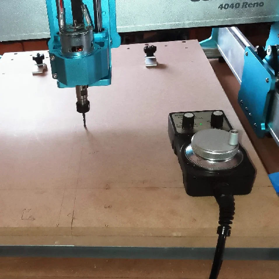 Testen mit der Genmitsu 4040 Reno CNC-Fräse
15. August 2025 -
-
![[Teil 2] Wie der SainSmart 3020-ULTRA zum MVP unserer Robotertechnik wurde [Teil 2] Wie der SainSmart 3020-ULTRA zum MVP unserer Robotertechnik wurde](//de.sainsmart.com/cdn/shop/articles/How_the_SainSmart_3020-ULTRA_Became_the_MVP_of_Our_Robotics_Workshop_1.webp?v=1754296870)
-
-


![[Teil 2] Wie der SainSmart 3020-ULTRA zum MVP unserer Robotertechnik wurde [Teil 2] Wie der SainSmart 3020-ULTRA zum MVP unserer Robotertechnik wurde](http://de.sainsmart.com/cdn/shop/articles/How_the_SainSmart_3020-ULTRA_Became_the_MVP_of_Our_Robotics_Workshop_1.webp?v=1754296870)

